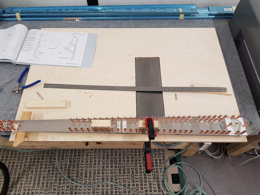
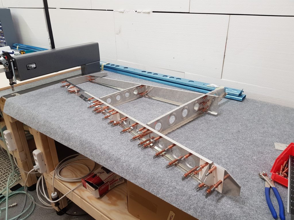
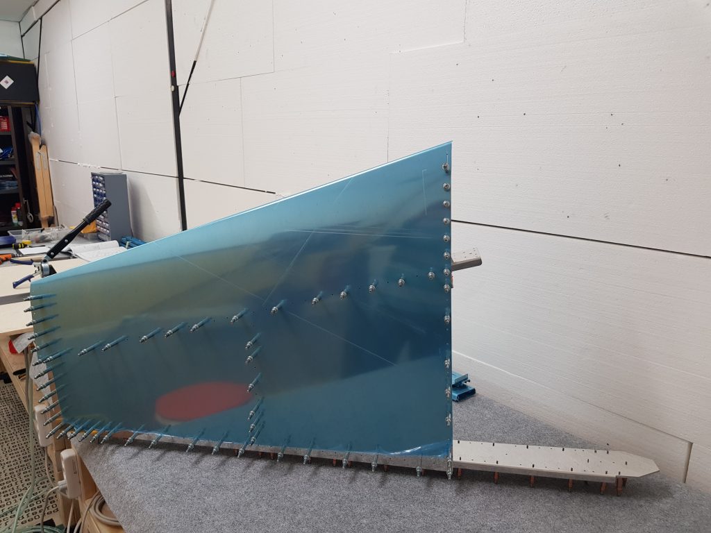
As per plans construction starts with the vertical fin. Having read the instructions many times and respective builder logs identification of parts and the first steps turned out to be more easy and handy as expected. Nevertheless deburring is time consuming – and appropriate technique looks to become key to work progress and a quality built ….
Deburring holes seems to be most efficient using either the speed duburring tool and countersinks or a standard drill 7-9mm and spinning it between your fingers. Before the edge deburring tool can be applied the edges need to be flat and smoothed which in my case is best achieved by a vixen file or sandpaper. For the time being I also finally sand the edges to get a nice and smooth radius on the corners and edges.
Being warned by some fellow builders to read instructions from VANS word by word and tick every action noted afer completion – the first mouse-trap flush rivet orientation on VS-902 and VS doubler was mastered successfully.
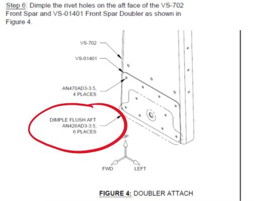
As a first result the doubler and spart were dimpled using the 3/32 dimple dies and the DDRT2. As a learning from the training project and a very smart advice from Cleaveland Aircraft Tool (https://www.youtube.com/watch?v=Qo9QCMaNSoA) a proper set dimple shall be crisp with little change of relected light (halo) around the dimple. My technique developed is to dimple by pressing the lever twice (without lifting inbetween) and by doing so achieve more crispy set dimples.
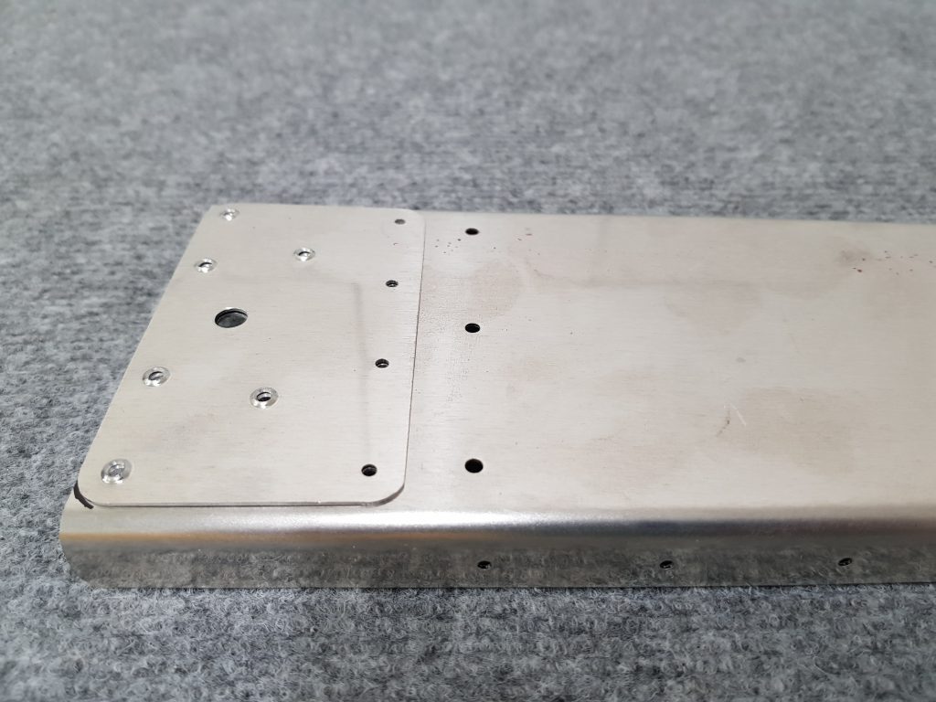
Next step preparing the vertical stab rear spar. Although manual advices not to straighten the doubler I did so using the technique described in Section 5.13.1 „WANG“. Completion of these steps also requires a new (to me) technique for sountersinks using a microstop countersink tool.
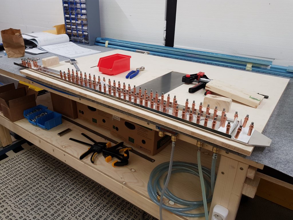
Unfortunately I was not well organized and fully familiarized with the very complete tool set sourced from planetools. As shown below I used the #30 countersink bit instead of a 1/8. Maybe not being so much used to the imperial metrics – I overlooked checking the bits for the label which should have warned me prior to their application. Fortunately I hadn’t dimpled full depth for a substructure dimple (see section 5.5) and managed to „redrill“ with the proper 100°#30 bit ending a lightly deeper countersink than recommended (around .011inch).
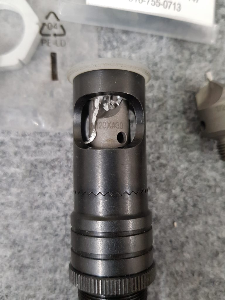
Not really satisfied with the scotch deburring wheel attached to an extension of my bench grinder – deburring on the parts of the VS was a mix of sanding, edge deburring tool, file. Meanwhile I fitted the workshop with another bench grinder replacing one of the wheels with the scotch deburring wheel. Attaching the wheel required me to fabricate a center piece from POM (on may EMCO lathe in my homeshop). Spinning is now smooth and free of vibration. Completion of the VS step by step with manual instructions were not difficult although some of the steps – intruducing new techniques like fluting, flange bending, etc- requires time and practice to end up @ a state of acceptable quality. Altough mentioned by so many fellow builders, accuracy of the parts manufactored from VANs is astonishing – and in case something does not match or fit – the failure needs to be looked up at the steps completed by the builder – either by not fully understanding or following the instructions or by failure or poor quality of execution.
Finally after a couple of work sessions the steps ended in a prefitted VS – all parts still not primed. As temperatures in December are low and the workshop does not allow for spraying at all – I decided to proceed with the rudder and other parts of the empenage kit before refocusing again on the VS.
In early March 2020 the ambient temperatures rised to 15-18°C which allowed me to grab lots of the already prepared parts (VS and rudder) for a priming session.


